Containerized Integrated MBR Device
Containerized Integrated MBR Device
1. Process Flow and Description

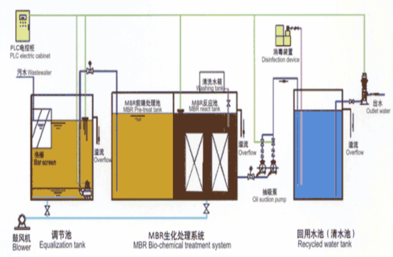
Figure 1: Process Flow Diagram
The containerized integrated Membrane Bioreactor (MBR) device is an integrated sewage treatment and reuse device that takes the membrane bioreactor as the main treatment process, integrating the functions of sewage treatment and reuse.
Sewage flows through a grid or hair filter (mechanical grid or manual grid) with a grid gap of 1-3 mm to remove large - particle suspended solids and impurities, and then flows into the sewage equalization tank. In the equalization tank, the water quality and quantity are adjusted. The sewage is lifted to the anoxic tank by the sewage lift pump, and after hydrolysis and acidification in the anoxic tank, it flows into the MBR biochemical treatment system. The entire biochemical treatment system consists of a front - end treatment unit and a reaction tank. Whether the front - end treatment tank is needed and its design depend on the influent water quality and effluent requirements. The reaction tank is filled with hollow fiber membranes, forming an MBR - aerobic operation mode.
The effluent from the MBR reaction tank can directly enter the reuse water tank, where disinfection is carried out using ultraviolet (UV) light or chlorine dioxide. After various water quality indicators meet the standards, the water can be discharged or pumped into the reclaimed water pipe network for reuse.
2. Unit Composition and Description
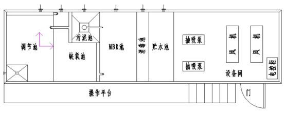
Figure 2: Typical Layout Diagram
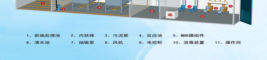
The containerized integrated MBR device is mainly composed of the following five units:
(1) Front - end treatment tank;
(2) MBR biochemical reaction tank;
(3) Sludge tank;
(4) Clear water disinfection tank;
(5) Equipment room. The descriptions of each unit are as follows:
(1) Front - end treatment tank: The front - end treatment tank is mainly an anoxic tank (the equalization tank can be placed inside or outside the container according to actual needs). One side of the anoxic tank is provided with a water inlet, and the upper part of the other side is provided with a weir trough and a water outlet, which allows sewage to flow into the membrane bioreactor tank stably and naturally. The Hydraulic Retention Time (HRT) of sewage in the anoxic tank is 3 - 8 hours. By intermittently supplying oxygen, acidification, nitrification, and denitrification are effectively carried out, so that organic matter is gradually converted into inorganic matter and degraded and removed. A manhole is opened at the top of the anoxic tank, and a steel vertical ladder is installed to facilitate operation and maintenance.
(2) MBR biochemical reaction tank: One side of the tank is provided with a water inlet. The reaction tank is equipped with hollow fiber membrane modules and contains activated sludge. The surrounding aeration and membrane sheet aeration pipelines are connected to the fan, and the water collection pipe supporting the membrane module is connected to the suction pump. The sewage to be treated enters the MBR biochemical reaction tank through the water inlet, and the HRT of the sewage in the reaction tank is 5 - 8 hours. After being degraded by the activated sludge in the reaction tank, the sewage passes through the anti - fouling membrane module and is then sucked out by the suction pump into the clear water disinfection tank. The reaction tank is also equipped with a sludge lift pump, which can lift excess sludge into the sludge tank; an overflow port is opened at the upper part of the reaction tank to allow sewage to flow into the equalization tank by gravity; an emptying port is opened at one side of the lower part to facilitate the maintenance and cleaning of the internal structure of the tank.
(3) Sludge tank: A sludge collection hopper is installed at the bottom of the sludge tank, and a sludge collection pipe is set up to facilitate the concentration of sludge. A weir trough is arranged at the upper part to facilitate the return of the supernatant to the MBR tank. A sludge discharge port is opened at the bottom, which can realize automatic sludge discharge by static pressure, and a sludge pump can also be installed for sludge discharge.
(4) Clear water disinfection tank: An overflow drain port is arranged at the upper part of the clear water disinfection tank. The disinfection measures for the disinfection tank adopt chlorine dioxide or UV light to further purify the water quality.
(5) Equipment room: The equipment operation room is equipped with two fans, which automatically switch every 12 hours of operation. The fans are provided with noise reduction and vibration damping measures; the surrounding walls and ventilation ports of the equipment room are equipped with sound absorption and shockproof materials; two suction pumps; one set of disinfection devices; a remote frequency - conversion water supply system (the frequency - conversion water supply system includes a water supply pump, a pressure stabilizing tank, etc.) can be set up according to actual requirements; one PLC control cabinet and a lighting system; a door is opened at the front end of the equipment room, and a rainproof air inlet and a ventilation and convection device are arranged at the top.
The above units are integrally arranged in a single container, and the operation of each power equipment is automatically controlled by the PLC in the electric control cabinet.
3. Product Features
• This device has a containerized function: it integrates the anoxic tank, MBR biological reaction tank, sludge tank, clear water tank, and equipment operation room into a large container. It has a compact structure, a simple process flow, a small floor area (only 1/3 - 1/2 of that of the traditional process), convenient capacity expansion, a high degree of automation, easy operation and maintenance, and can be moved anywhere at any time. That is, this device can be directly transported to the location of the treatment target for large - scale treatment directly without secondary construction.
• It integrates the sewage treatment and water purification process flows into the same device, which can be buried shallowly underground or placed on the ground surface; basically, no sludge is generated during the treatment process, so it has no impact on the surrounding environment; it has a good operation effect, high reliability, stable effluent quality, and low operation cost.
• When treating municipal sewage, it has strong impact load resistance, high pollutant removal efficiency, and strong nitrification capacity. It can carry out nitrification and denitrification at the same time, and has the functions of nitrogen and phosphorus removal. It is very suitable for treating municipal sewage and decentralized sewage. The effluent can be reused or directly discharged up to the standard, and can meet the different water quality requirements of different users.
• The aeration pipeline of the membrane biological reaction tank is divided into two paths: one path is used for aerating the surrounding activated sludge, and the other path is used for aerating the membrane sheets of the membrane module. Its advantage is that the scouring force generated by aerating the membrane sheets makes the membrane sheets beat each other, which can shake off the sludge attached to the surface of the membrane pores, greatly improving the membrane flux, prolonging the service life of the membrane, and thus reducing the operation cost.
4. Uses and Application Scope
Uses
• Upgrading and transformation of existing sewage treatment plants and waterworks
• New construction of municipal sewage treatment plants and waterworks
• Pretreatment for pure water production
• Reclaimed water reuse
Application Scope
• Domestic sewage treatment and reuse in hotels, restaurants, and residential communities
• Domestic sewage reuse in industrial and mining enterprises, remote rural areas, outposts, and tourist attractions
• Various industrial wastewaters similar in nature to domestic sewage (hospital wastewater, pharmaceutical wastewater, washing wastewater, food wastewater, cigarette wastewater, etc.)
Table 1: Treatment Effect of Integrated MBR
Item | Influent Water Quality | Effluent Water Quality |
BOD5 (mg/L) | After pretreatment, the biodegradability BOD5: CODcr ≥ 0.3 | ≤ 10 |
CODcr (mg/L) | - | ≤ 50 |
Turbidity (NTU) | - | ≤ 1 |
SS (mg/L) | - | ≤ 5 |
PH | - | 6 - 9 |
5. Equipment List of Integrated MBR Device
Table 2: Equipment List of 5m³/h Integrated MBR Device
Serial Number | Name | Specification | Unit | Quantity | Remarks |
1 | Equalization Tank | 30m³ | Set | 1 | Can be placed inside or outside the container |
2 | Submersible Sewage Pump | Q = 6m³/h, H = 5m | Unit | 1 | Can be placed inside or outside the container |
3 | Hair Filter | Q = 5m³/h | Unit | 1 | Can be placed inside or outside the container |
4 | Anoxic Tank | 15m³ | Set | 1 | Set up according to needs |
5 | MBR Reaction Tank | 25m³ | Set | 1 | - |
6 | MBR Membrane Module | KF - MBR - 12PVC | Sheet | 36 | - |
7 | Self - priming Pump | Q = 6m³/h, H = 5m, Suction Lift: 8m | Unit | 2 | Can also be used for backwashing |
8 | Sludge Pump | Q = 2m³/h, H = 5m | Unit | 1 | Centrifugal pump |
9 | Fan | Q = 2.91m³/min, P = 34.3Kpa | Unit | 2 | - |
10 | Clear Water Tank | 10m³ | Set | 1 | - |
11 | Reclaimed Water Reuse Pump | Q = 6m³/h, H = 5m, Centrifugal pump | Unit | 2 | Set up according to needs |
12 | Rotor Flowmeter | 0 - 10m³/h | Unit | 2 | - |
13 | Float Level Switch | - | Unit | 2 | - |
14 | Electric Contact Pressure Gauge | 0 - 0.1Mpa | Piece | 2 | - |
15 | Pressure Gauge | 0 - 0.6Mpa | Piece | 6 | - |
16 | Turbidity Meter | 0 - 50NTU | Unit | 1 | Set up according to needs |
17 | Valves and Pipes | - | Set | 1 | - |
18 | Electrical System | - | Set | 1 | - |
19 | PLC Control System | - | Set | 1 | - |
20 | Equipment Integration Container | 12m × 2.4m × 2.5m | Unit | 1 | Estimated value |
| Total | - | - | - | - |
Table 3: Equipment List of 10m³/h Integrated MBR Device
Serial Number | Name | Specification | Unit | Quantity | Remarks |
1 | Equalization Tank | 60m³ | Set | 1 | Placed outside the container |
2 | Submersible Sewage Pump | Q = 12m³/h, H = 5m | Unit | 1 | Placed outside the container |
3 | Hair Filter | Q = 10m³/h | Unit | 1 | Can be placed inside or outside the container |
4 | Anoxic Tank | 25m³ | Set | 1 | Set up according to needs |
5 | MBR Reaction Tank | 50m³ | Set | 1 | - |
6 | MBR Membrane Module | KF - MBR - 12PVC | Sheet | 72 | - |
7 | Self - priming Pump | Q = 12m³/h, H = 5m, Suction Lift: 8m | Unit | 2 | Can also be used for backwashing |
8 | Sludge Pump | Q = 3m³/h, H = 5m | Unit | 1 | Centrifugal pump |
9 | Fan | Q = 5.9m³/min, P = 34.3Kpa | Unit | 2 | - |
10 | Clear Water Tank | 20m³ | Set | 1 | - |
11 | Reclaimed Water Reuse Pump | Q = 12m³/h, H = 5m, Centrifugal pump | Unit | 2 | Set up according to needs |
12 | Rotor Flowmeter | 0 - 15m³/h | Unit | 2 | - |
13 | Float Level Switch | - | Unit | 2 | - |
14 | Electric Contact Pressure Gauge | 0 - 0.1Mpa | Piece | 2 | - |
15 | Pressure Gauge | 0 - 0.6Mpa | Piece | 6 | - |
16 | Turbidity Meter | 0 - 50NTU | Unit | 1 | Set up according to needs |
17 | Valves and Pipes | - | Set | 1 | - |
18 | Electrical System | - | Set | 1 | - |
19 | PLC Control System | - | Set | 1 | - |
20 | Equipment Integration Container | 15m × 2.4m × 2.5m | Unit | 1 | Estimated value |
| Total | - | - | - | - |
6. Control Instructions
1. The lift pumps of the equalization tank are used one by one as a standby. Controlled by the liquid level switch of the equalization tank, they start automatically with high - low level limits. Both pumps run at high liquid level, stop at low liquid level, and one pump runs at normal liquid level, with automatic switching every 12 hours of operation.
2. There is one sludge pump, which is controlled manually.
3. The suction pumps are used one by one as a standby. Controlled by the liquid level switch of the MBR biochemical tank, they run normally at high liquid level, overflow naturally at ultra - high liquid level, and stop at low liquid level. Under normal circumstances, they operate according to the rule of running for 8 minutes and stopping for 2 minutes, with automatic switching every 12 hours of operation.
4. The fans are used one by one as a standby. Under normal circumstances, the fans run continuously. To extend their service life, the two fans are used alternately, with automatic switching every 12 hours of operation. If an anoxic tank is set up, the air supply to the anoxic tank is intermittent aeration, controlled by a solenoid valve, with air supply once every 4 hours, 10 minutes each time.
5. If a reclaimed water reuse pump is set up, it is controlled manually.
6. The disinfection device is linked with the suction pump.
7. If there is little or no sewage, to ensure the normal growth of microorganisms and prevent the biofilm from dying and falling off, the fan can be started intermittently. The start - up cycle can be selected arbitrarily within 2 hours, and the start - up time can be selected arbitrarily within 30 minutes.
8. The electrical control equipment is equipped with an alarm device and a working status display system, which can be controlled automatically or manually.
Attached Figures: Containerized Integrated MBR Device