Lined reinforced polyvinylidene fluoride hollow fiber curtain membrane box(MBR Application design of membrane box)
Brief introduction to the application design of reinforced polyvinylidene fluoride hollow fiber curtain membrane cassette (MBR cassette ) with inner lining
Lined reinforced polyvinylidene fluoride hollow fiber curtain membrane cassettes (MBR cassettes ) are generally applied using membrane bioreactor (MBR ) technology. Like traditional activated sludge processes , MBR technology ultimately decomposes organic matter in the raw water by microorganisms. Lined reinforced polyvinylidene fluoride hollow fiber curtain membrane modules ( MBR membranes ) primarily separate biodegradable wastewater from sludge. Therefore, prior design, it is important to fully consider factors such as the biodegradability of the wastewater to be treated, influent water quality, and effluent requirements, before determining the appropriate process and related design parameters.For large-scale lined reinforced polyvinylidene fluoride hollow fiber curtain membrane cassette (MBR cassette ) application projects, especially for industrial wastewater with complex components, it is best to conduct sufficient small or pilot tests to explore and verify before determining the process and design parameters.
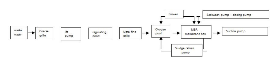
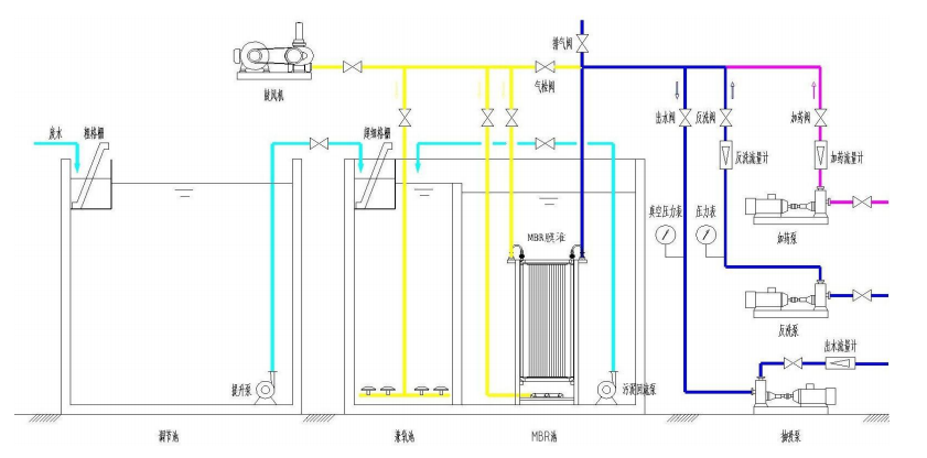
Typical process flow diagram of membrane bioreactor (MBR)

Preprocessing
the liner-enhanced polyvinylidene fluoride hollow fiber curtain membrane box (MBR membrane box )includes two parts: the pretreatment of the traditional activated sludge method and the pretreatment of protecting the liner-enhanced polyvinylidene fluoride hollow fiber curtain membrane assembly (MBR membrane ).
Pretreatment of traditional activated sludge process
Note! (1) Removal of particulate matter: coarse screens, fine screens, and grit chambers, etc.
Note!(2) Water quality and quantity adjustment: regulating tank, adding acid and alkali to adjust pH value, flocculation and sedimentation, etc.
Note!(3) Biodegradable treatment: micro-electrolysis, hydrolysis acidification, anaerobic, facultative aerobic and contact oxidation, etc.
Pretreatment of protective tape lined reinforced polyvinylidene fluoride hollow fiber curtain membrane module (MBR membrane )
Note! (1) Oil removal facilities: If the wastewater to be treated contains grease or mineral oil, special oil removal facilities ( such as adsorption and gasThe grease content is reduced to < 50 mg/l and the mineral oil content is reduced to < 3 mg/l. This is because as filtration proceeds, grease and mineral oil components are extensively adsorbed onto the membrane surfaces of the reinforced polyvinylidene fluoride hollow fiber curtain membrane module (MBR membrane) with an inner lining , thereby clogging the micropores on the membrane surface and causing irreparable membrane fouling.
Note! (2) Ultra-fine screen: If the wastewater to be treated contains hair and fibrous matter, it is necessary to equip the conventional coarse screen (20-25mm) and fine screen.the screen (5-10mm) , an ultra-fine screen with a pore size of 1mm is also required . This is because hair and fibrous materials can easily entangle on the membrane wires of the reinforced polyvinylidene fluoride hollow fiber curtain membrane module (MBR membrane ) with an inner lining, causing the membrane wires to clump and cause active sewage.Mud clumps block the membrane fibers or the membrane fibers break, affecting the water output and water quality.
Note! (3) Defoamer: If the system sludge foams a lot and needs to add defoamer, only high-grade ethanol series defoamer can be used. It is strictly forbidden to use Silica gel defoamers. This is because as filtration progresses, silica gel defoamers will be widely adsorbed on the surface of the membrane fibers of the reinforced polyvinylidene fluoride hollow fiber curtain membrane module (MBR membrane) with an inner lining, thereby blocking the micropores on the surface of the membrane fibers and causing irreparable membrane fouling.
Note! (4) Coagulants and flocculants: If coagulants and flocculants are used in the pre-treatment of the system ( especially high molecular weight flocculants Acrylamide (PAM), etc.) should be avoided from entering the membrane tank of the membrane bioreactor (MBR). This is because as filtration progresses, the coagulant and flocculant will be widely adsorbed on the surface of the membrane fibers of the reinforced polyvinylidene fluoride hollow fiber curtain membrane module (MBR membrane ), thereby clogging the micropores on the membrane fiber surface and causing irreparable membrane fouling.
Note! (5) Activated sludge: The sludge concentration tolerance of the reinforced polyvinylidene fluoride hollow fiber curtain membrane box (MBR membr a n e box ) is3000-15000mg/l, with an optimum value of 7000-12000mg/l. A sludge concentration that is too low will affect the system's treatment effect, while a sludge concentration that is too high will exacerbate the fouling of the reinforced polyvinylidene fluoride hollow fiber curtain membrane module (MBR membrane) with an inner lining, thereby affecting the normal operation of the system .
Lined reinforced polyvinylidene fluoride hollow fiber curtain membrane box (MBR membrane box )
Selection
reinforced polyvinylidene fluoride hollow fiber curtain membrane cassettes (MBR cassettes ) with inner linings based on the water quality and quantity of the wastewater to be treated, the size of the membrane pool, and the piping layout. For details, please consult our relevant technical personnel. The following is a selection guide based on a daily treatment capacity of 120 tonsofconventional domestic wastewater :
A. Design membrane flux for domestic wastewater: 20LMH
B. Actual operation and water production time of MBR system per day : 19.2h ( systemonfor8 minutes,offfor2 minutes)
C. Daily sewage treatment capacity: 120t = 120 × 1000L = 120,000L
D. Required membrane area: 120000L ÷ 20LMH ÷ 19.2h = 312.5 m2
E. For common curtain film models and areas, please refer to Section 3.4 of this manual.
F. Required number of curtain films = required film area ÷ single type film area
JL-MBR-8-CO-PVDF type, single membrane area 8 m2;
Thenumberof curtain films required=312.5÷8=39.06 pieces,rounded upto40pieces , andsoon:
JL-MBR-10-CO-PVDF type, single membrane area 10m2; 32pieces are requiredforroundingJL-MBR-15-CO-PVDF
type, single membrane area 15m2; 21pieces are requiredforrounding
G.Calculate the membrane box size basedon the numberof curtain membranes, see Table 1.3.bbelow
H. Determine the model andquantityof curtain membrane basedon membrane pool size, manufacturer recommendation, stockingspeed, inventory status, etc.
Table 1.3.b——MBR membrane support+ MBR membrane specifications
| Parameter Item | JL-MZJ-N-PVDF-8 | JL-MZJ-N-PVDF-10 | JL-MZJ-N-PVDF-15 |
|---|
| Water Flow | 120 m³/d | 120 m³/d | 120 m³/d |
| Diaphragm Quantity (N) | 40 pieces | 32 pieces | 21 pieces |
| Total Membrane Area | 320 m² | 320 m² | 315 m² |
| Water Collection Pipe | DN40 | DN40 | DN40 |
| External Aeration Pipe | DN40 | DN40 | DN40 |
| Internal Aeration Main Pipe | DN40 | DN40 | DN40 |
| Membrane Box Length | Calculation formula: N×90+100
Actual dimension: 3700 mm (can be divided into another group) | Calculation formula: N×90+100
Actual dimension: 2980 mm | Calculation formula: N×90+100
Actual dimension: 1990 mm |
| Membrane Box Width | 900 mm | 900 mm | 900 mm |
| Membrane Box Height | 1500 mm | 2000 mm | 2000 mm |
| Membrane Box Dry Weight | 480 kg | 450 kg | 350 kg |
Arrangement
The MBR membrane tank is generally designed by the design institute based on the sewage quality and water volume. ( During the design, it is strongly recommended to consider the offline chemical cleaning of the MBR membrane and design a dissolving and foaming tank equipped with offline chemical cleaning. The tank size should be at least large enough to accommodate one or more membrane boxes .)
The distance between membrane boxes: The distance between the membrane box with inner lining reinforced polyvinylidene fluoride hollow fiber curtain membrane (MBR membranebox ) and the membrane box with inner lining reinforced polyvinylidene fluoride hollow fiber curtain membrane (MBR membrane box ) should be ≥300mm.
The distance between the membrane box with lined reinforced polyvinylidene fluoride hollow fiber curtain membrane (MBR membrane box ) and the membrane bioreactor (MBR) pool wall should be ≥300mm.
The distance between the membrane box and the liquid level: The distance between the top of the membrane box with reinforced polyvinylidene fluoride hollow fiber curtain membrane (MBR membranebox) and the effective liquid level in the membrane bioreactor (MBR) pool should be ≥500mm.
Note! (1) The membrane of our company's conventionally produced reinforced polyvinylidene fluoride hollow fiber curtain membrane box (MBR membranebox ) with lining The frame isweldedfromSUS304 stainless steel square steel. If other materials are required, the user must inform us in advance.
Note! (2) Our company's conventionally produced reinforced polyvinylidene fluoride hollow fiber curtain membrane cassettes (MBR cassettes ) are all It is fixed to the bottom of the membrane bioreactor (MBR) tank by SUS304 stainless steel expansion screws . It does not include a lifting device. If a lifting device is required, the user must inform us in advance.
Supporting facilities for reinforced polyvinylidene fluoride hollow fiber curtain membrane cassette (MBR cassette ) with lining
The user is required to prepare the supporting facilities of the reinforced polyvinylidene fluoride hollow fiber curtain membrane cassette (MBR cassette ) with an innerlining. Ifthe userrequiresour company to configure it on their behalf, the user must inform our relevant personnel in advance.
blower
The blower is used to provide oxygen to the microorganisms in the membrane bioreactor (MBR) tank and purge the membrane cassettes (MBR cassettes) with reinforced polyvinylidene fluoride hollow fiber curtain membranes. The ratio of the total aeration volume of these two components to the total water output of the membrane bioreactor (MBR) is called the air-to-water ratio. The recommended air-to-water ratio is 20:1 to 30:1. The blower outlet is connected to the internal aeration main pipe and external aeration pipe of the MBR cassettes.
PD r u m = P1 + P2 + K × P3 + P4, unit : kPa
P1: Gas transmission pipeline pressure loss
P2: Gas distribution pipeline pressure loss
P1+P2: Generally 2 kPa
P3: Water depth from the lowest point of the gas distribution pipe to the air overflow surface x 10 kPa K Coefficient: Generally take 1.1
P4: full pressure, generally 5 kPa
Q is the designed daily processing capacity of the membrane bioreactor (MBR), unit : m3 /d
Note! (1)The blower is an important supporting equipment for the normal operation of the membrane bioreactor (MBR). When the blower fails or stops for any other reason, the suction pump must be stopped at the same time. Because when the blower stops, if the suction pump continues to work, sludge will accumulate rapidly on the membrane surface, causing the suction pressure of the suction pump to rise sharply, and even causing the system to crash.
Note! (2) In order to facilitate the operation and management of membrane bioreactor (MBR) , it is recommended to use reinforced polyvinylidene fluoride lining.
The hollow fiber curtain membrane box (MBR membranebox) is equipped with a dedicated blower。
Suction pump
The suction pump is used to suck out the water intercepted and filtered by the lined reinforced polyvinylidene fluoride hollow fiber curtain membrane assembly (MBR membrane ) and discharge it or enter the next treatment unit. The inlet of the suction pump is connected to the water collection pipe of the lined reinforced polyvinylidene fluoride hollow fiber curtain membrane box (MBR membrane box ) .
Q is the designed daily processing capacity of the membrane bioreactor (MBR), unit : m3 / d
Note! (1) We recommend that the suction pump be installed so that the water inlet is lower than the water level in the membrane bioreactor (MBR) pool. The effective water level can ensure the long-term stable operation of the suction pump, but this installation method should be careful to prevent siphoning.
Note! (2) If the water inlet of the suction pump is higher than the effective water level in the membrane bioreactor (MBR) tank, it is best to A water diversion tank is installed at the water inlet of the suction pump to ensure the long-term stable operation of the suction pump.
Note! (3) When the suction pump is first used, it should be filled with water and exhausted, otherwise the suction pump may not be able to suck out water. Intermittent operation may also damage the suction pump itself.
Note! (4) The suction pump should be equipped with a frequency converter or regulating valve to ensure that the outlet water of the membrane bioreactor (MBR) is a constant flow. Measure the water.
Backwash pump
the effluent or tap water of the lined enhanced polyvinylidene fluoride hollow fiber curtain membrane assembly (MBR membrane ) to flush the lined enhanced polyvinylidene fluoride hollow fiber curtain membrane assembly (MBR membrane ). The inlet of the backwash pump is connected to the effluent pool or tap water pipe of the membrane bioreactor (MBR) , and the outlet of the backwash pump is connected to the water collection pipe of the lined enhanced polyvinylidene fluoride hollow fiber curtain membrane box (MBR membranebox ).
Flow rate: Q = Q x 1.5-2, unit : m 3 /h
Lift: 10-15 meters
Material: The part in contact with water should be SUS304 stainless steel or other anti-corrosion materials
Note! (1) The backwash pump should be equipped with a frequency converter or a regulating valve to ensure that the flow rate and pressure during backwashing are within the design values.
Note! (2) The water source for the backwash pump must be clean and pollution-free, generally the effluent from the membrane bioreactor (MBR) or tap water.
Dosing pump (not recommended )
The dosing pump is used to pump the cleaning liquid in the dosing box into the membrane fibers of the reinforced polyvinylidene fluoride hollow fiber curtain membrane assembly (MBR membrane ) with lining for cleaning. The inlet of the dosing pump is connected to the dosing box, and the outlet of the dosing pump is connected to the membrane box of the reinforced polyvinylidene fluoride hollow fiber curtain membrane with lining.
(MBR membranebox) is connected to the water collecting pipe.
Flow rate: (2L/ m2 x membrane area) x 2, unit : L/h
Lift: 1-10 meters
Material: The part in contact with the cleaning fluid should be SUS316L stainless steel or other anti- corrosion materials
Note! (1)The dosing pump must be resistant to strong acids and alkalis.
Note! (2)The volume of the dosing box should be greater than [(2L/m 2 x membrane area) + dosing line volume].
Note! (3)The design of the dosing box should fully consider the storage conditions of the cleaning fluid. 5.5.5Instruments Required instruments for reinforced polyvinylidene fluoride hollow fiber curtain membrane cassettes (MBR cassettes ) include outlet vacuum pressuregauges,outlet flow meters, air flow meters, and liquid level gauges. Other instruments such as online pH meters, online turbidity meters, and onlineCOD meters are configured according to user needs
The outlet vacuum pressure gauge can also be an electric contact vacuum pressure gauge or a differential pressure sensor. It is mainly used to monitor the fouling of the reinforced polyvinylidene fluoride hollow fiber curtain membrane module (MBR membrane ). The outlet vacuum pressure gauge is generally installed on the outlet pipe parallel to the upper water collection pipe of the reinforced polyvinylidene fluoride hollow fiber curtain membrane cassette (MBR cassette ).
The outlet flow meter is mainly used to monitor the outlet water volume of the reinforced polyvinylidene fluoride hollow fiber curtain membrane box (MBR membranebox ) with inner lining. A regulating valve needs to be installed after the outlet flow meter to adjust the outlet water volume.
The air flow meter is mainly used to monitor the aeration volume of the reinforced polyvinylidene fluoride hollow fiber curtain membrane box (MBR membranebox ) with an inner lining. A regulating valve needs to be installed after the air flow meter to adjust the aeration volume.
Liquid level gauges are primarily used to monitor the liquid level within the membrane bioreactor (MBR) tank and control the coordinated operation of the raw water pump and suction pump. Liquid level gauges are generally designed with three liquid levels: high, medium, and low. The specific coordinated control is as follows: when the water level within the membrane bioreactor (MBR) tank falls below the low level, the suction pump stops operating; when the water level falls below the medium level, the sewage lift pump starts operating; when the water level rises above the medium level, the suction pump starts operating; and when the water level rises above the high level, the sewage lift pump stops operating .
Electronic Control System
The electronic control system is mainly used to control equipment such as blowers, suction pumps, backwash pumps, dosing pumps and liquid level gauges. For specific control methods, please refer to the operating instructions of each equipment or consult relevant technical personnel of our company.